
Technical resources
Pump Technology
Pump terminology, operating principles, performance references, formulas, examples, and diagrams.
Atmospheric Pressure
Atmospheric Pressure @ Sea Level
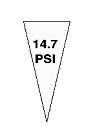

Absolute Pressure
The sum of the available atmospheric pressure and the gage pressure in the pumping system
Absolute Pressure (PSIA) = Gauge Pressure + Atmospheric Pressure
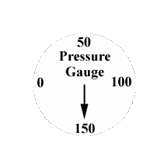
Absolute P. = 150 PSIG (Gauge P.) + 14.7 PSI (Atmospheric P.) = 164.7 PSIA
Vacuum
The full or partial elimination of Atmospheric Pressure
Atmospheric Pressure on the Moon = 0 = Full Vacuum
1 Inch Hg Vacuum = 1.13 Ft of Water
Specific Gravity
Specific Gravity is the ratio of the weight of anything to the weight of water.
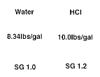
Specific Gravity of HCl = (Weight of HCl)/(Weight of Water) = (10.0)/(8.34) = 1.2
Pressure and Liquid Height Relationship (Head)
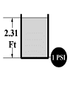
1 PSI = 2.31 Ft of Water
Pressure, Liquid Height, & Specific Gravity Relationship
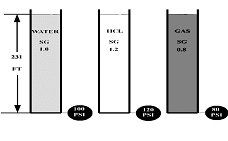
Pressure (PSI) = Head (FT) x Specific Gravity (SG) / 2.31
Example - Water - 231Ft x 1.0 / 2.31 = 100 PSI
Example - HCL - 231 Ft x 1.2 / 2.31 = 120 PSI
Example - Gas - 231 Ft x .80 / 2.31 = 80 PSI
Vapor Pressure
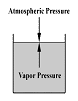
The pressure pushing against atmospheric pressure on liquids at elevated temperatures.
Suction Head
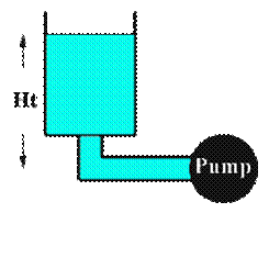
A Suction Head exists when the liquid is taken from an open to atmosphere tank where the liquid level is above the centerline of the pump suction, commonly known as a Flooded Suction.
Total Dynamic Head
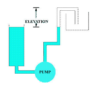
Total Dynamic Head (TDH) = Elevation(ft) + Friction(ft)
Centrifugal Pump Components
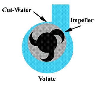
The two main components of a centrifugal pump are the impeller and the volute. The impeller produces liquid velocity and the volute forces the liquid to discharge from the pump converting velocity to pressure. This is accomplished by offsetting the impeller in the volute and by maintaining a close clearance between the impeller and the volute at the cut-water. Please note the impeller rotation. A centrifugal pump impeller slings the liquid out of the volute. It does not cup the liquid.
Pump Performance Curve
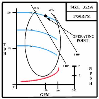
A Pump Performance Curve is produced by a pump manufacturer from actual tests performed and shows the relationship between Flow and Total Dynamic Head, the Efficiency, the NPSH Required, and the BHP Required.
Higher Head = Lower Flow Lower Head = Higher Flow
Lower Flow = Lower Horsepower Higher Flow = Higher Horsepower
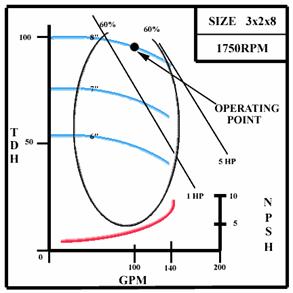
Based on Water SG 1.0
Capacity
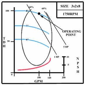
A Centrifugal Pump is a variable displacement pump. The actual flow rate achieved is directly dependent on the Total Dynamic Head it must work against.
The flow capacity of a centrifugal pump also depends on three (3) other factors:
1 Pump Design
2 Impeller Diameter
3 Pump Speed
Affinity Laws
The performance of a centrifugal pump is affected by a change in speed or impeller diameter.
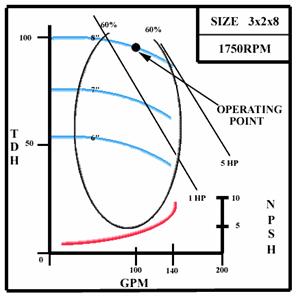
Q = Capacity (GPM) D = Impeller Diameter N= Speed(RPM)
H = Total Dynamic Head(Feet) BHP = Brake Horsepower
The affinity law for a centrifugal pump with the impeller diameter held constant and the speed changed:
Flow: Q1 / Q2 = N1 / N2
Example: 100 / Q2 = 1750/3500 Q2 = 200 GPM
Head: H1/H2 = (N1) x (N1) / (N2) x (N2)
Example: 100 /H2 = 1750 x 1750 / 3500 x 3500 H2 = 400 Ft
Horsepower (BHP):
BHP1 / BHP2 = (N1) x (N1) x (N1) / (N2) x (N2) x (N2)
Example: 5/BHP2 = 1750 x 1750 x 1750 / 3500 x 3500 x 3500 BHP2 = 40
The affinity law for a centrifugal pump with the speed held constant and the impeller diameter changed:
Flow: Q1 / Q2 = D1 / D2
Example: 100 / Q2 = 8/6 Q2 = 75 GPM
Head: H1/H2 = (D1) x (D1) / (D2) x (D2)
Example: 100 /H2 = 8 x 8 / 6 x 6 H2 = 56.25 Ft
Horsepower (BHP):
BHP1 / BHP2 = (D1) x (D1) x (D1) / (D2) x (D2) x (D2)
Example: 5/BHP2 = 8 x 8 x 8 / 6 x 6 x 6 BHP2 = 2.1
Brake Horsepower
BHP = Flow(GPM) X TDH(FT) x SG /3960xEFFICIENCY(%)
Example: BHP = (100 GPM) x (95 Ft) x (1.0) / 3960 x .6 BHP = 4.0
Calculating Total Dynamic Head (TDH)
Flooded Suction Application
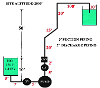
TDH = Total Discharge Head - Total Suction Head
Total Suction Head = Static - Friction
Total Discharge Head = Static + Friction
Suction Lift Application
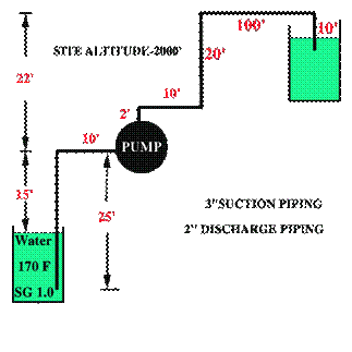
TDH = Total Discharge Head + Total Suction Lift
Total Suction Lift= Static + Friction
Total Discharge Head = Static + Friction
Total Dynamic Head = Total Discharge Head + Total Suction Head
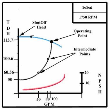
System Head Curve
To Calculate a System Head Curve several points must be chosen to calculate friction losses on both the suction and discharge sides of the pump at various flow rates. The static suction head/lift and the static discharge head remain constant.
Net Positive Suction Head
Net Positive Suction Head Required (NPSHR)
The net positive suction head required is a function of the pump design at the operating point on the pump performance curve.
Net Positive Suction Head Available (NPSHA)
The net positive suction head available is a function of the pump suction system.
The Net Positive Suction Head is the absolute total suction head in feet.
The NPSH available in a flooded suction system is:
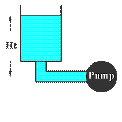
Atmospheric Pressure (-) Vapor Pressure (+) Liquid Height (-) Friction in the Suction Line.
The NPSH available in a suction lift system is:
Atmospheric Pressure (-) Vapor Pressure (-) Liquid Ht. (-) Friction in the Suction Line.
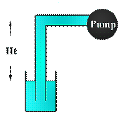
If the NPSHA < NPSHR the Pump will cavitate
Cavitation
Cavitation may occur in two different forms:
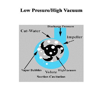
Suction Cavitation
Suction Cavitation occurs when the pump suction is under a low pressure/high vacuum condition where the liquid turns into a vapor at the eye of the pump impeller. This vapor is carried over to the discharge side of the pump where it no longer sees vacuum and is compressed back into a liquid by the discharge pressure. This imploding action occurs violently and attacks the face of the impeller. An impeller that has been operating under a suction cavitation condition has large chunks of material removed from its face causing premature failure of the pump.
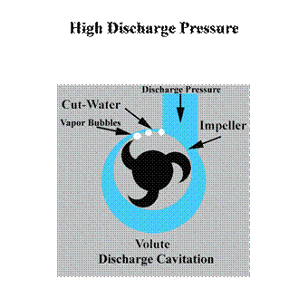
Discharge Cavitation
Discharge Cavitation occurs when the pump discharge is extremely high. It normally occurs in a pump that is running at less than 10% of its best efficiency point. The high discharge pressure causes the majority of the fluid to circulate inside the pump instead of being allowed to flow out the discharge. As the liquid flows around the impeller it must pass through the small clearance between the impeller and the pump cutwater at extremely high velocity. This velocity causes a vacuum to develop at the cutwater similar to what occurs in a venturi and turns the liquid into a vapor. A pump that has been operating under these conditions shows premature wear of the impeller vane tips and the pump cutwater. In addition due to the high pressure condition premature failure of the pump mechanical seal and bearings can be expected and under extreme conditions will break the impeller shaft.
Suction Cavitation & Discharge Cavitation are extremely damaging to pump components.